Creativeworks London Project – Iteration 2

This is the second in a series of posts documenting a project funded by an Entrepreneur-in-Residence Award from Creativeworks London. See an earlier post for the first design iteration.

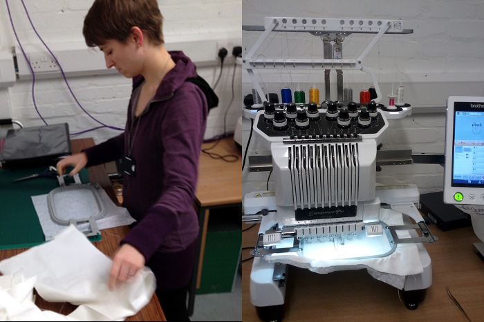
After working with the laser cutter and inkjet printer to bring some initial ideas to a physical form, I was ready to move on to the 3D printer. The Materials Processing Lab at Queen Mary has a Objet30 Prime which is printer that builds up a liquid layer of material that is then UV cured. It can print 16-28 microns per layer, depending the material being printed.
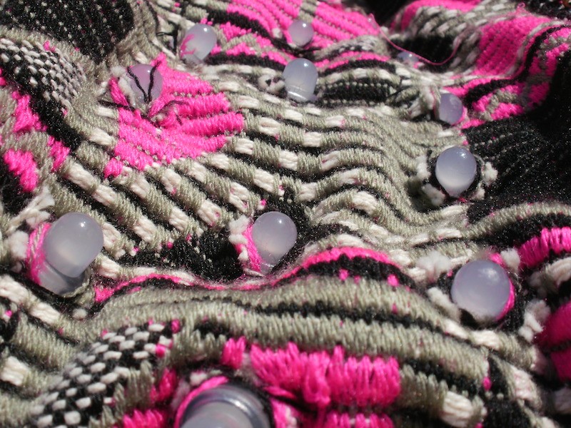
3D Printed Buttons

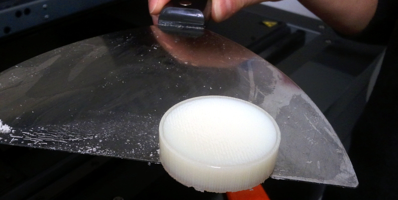
The biggest barrier to the 3D printer for me was learning how to create a model. I worked with AutoCAD and managed to learn enough from online tutorials to get what I wanted. I started by creating a solid cylinder, seen below in a hard white plastic, surrounded by a translucent material printed as a support structure.

Test print

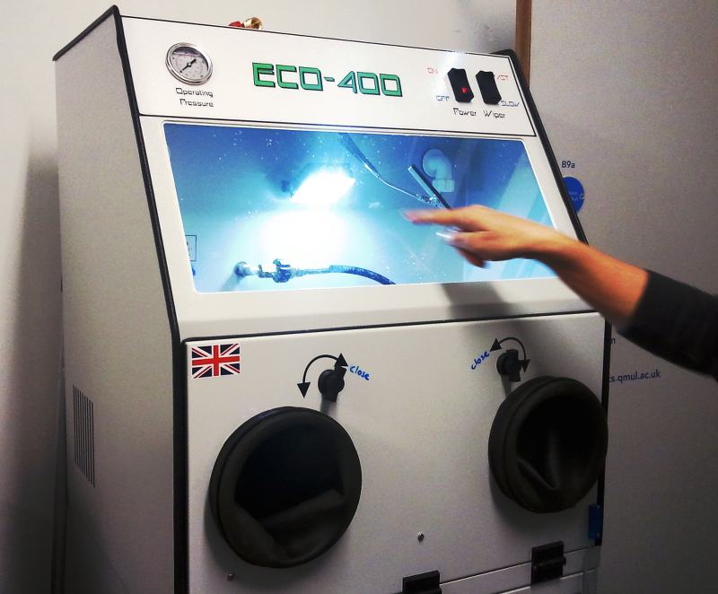
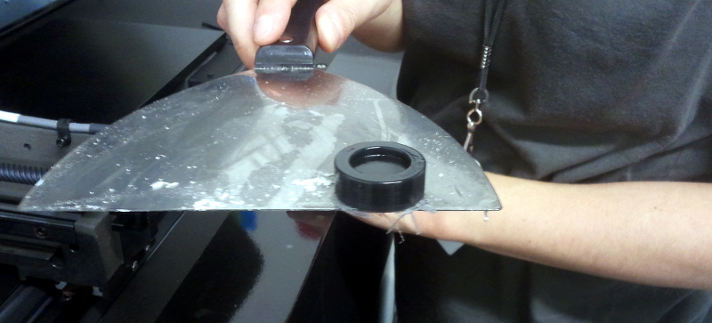
The support material is washed away in a power washing station. The station has a staggering number of significant design flaws, but its little automatic windshield wiper makes it endearing.

Washing station

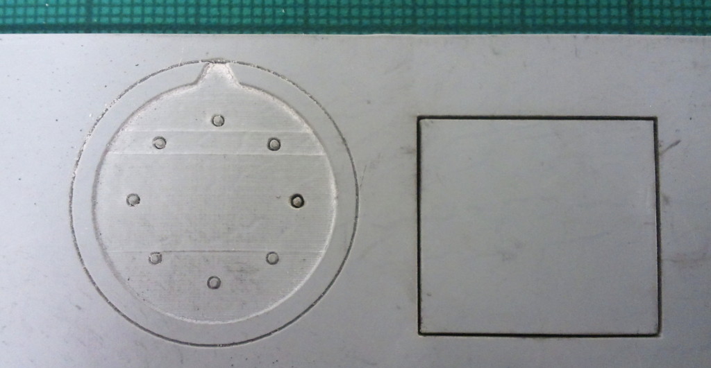
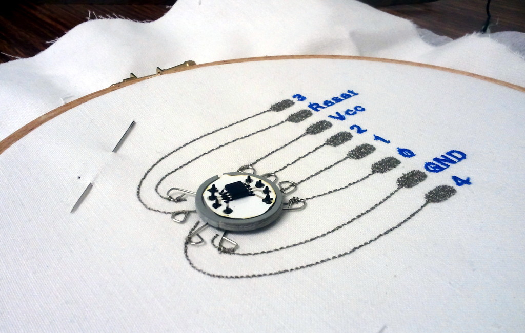
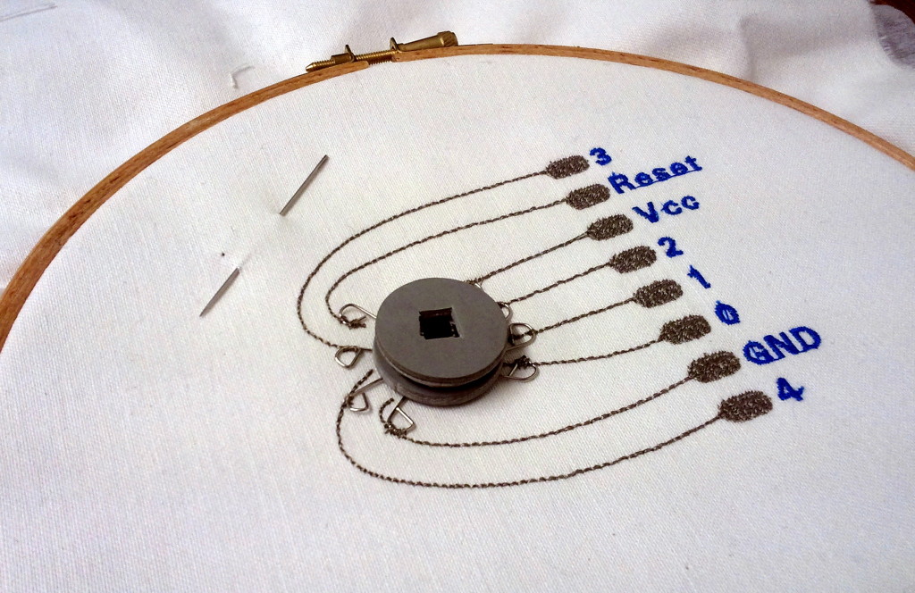
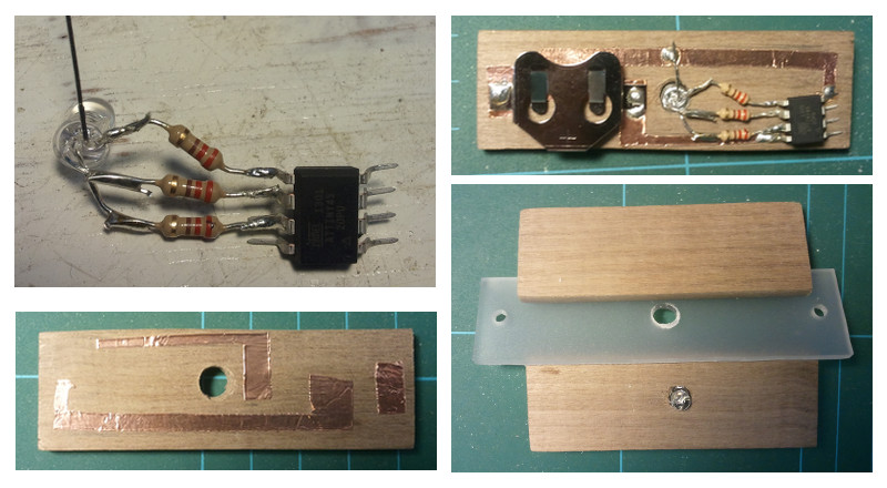
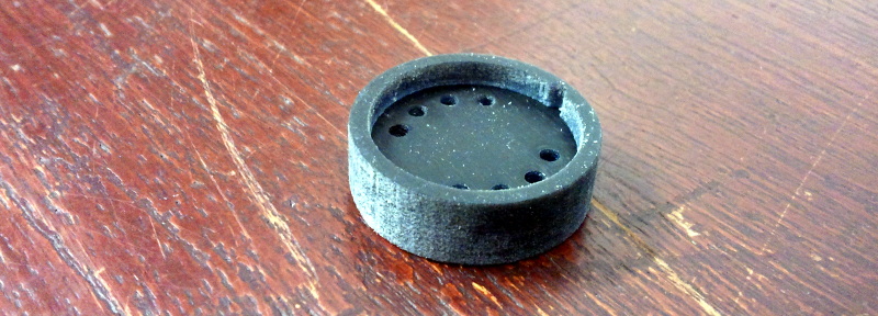
The initial printed design was a 3D interpretation of the laser cutter layout. Eight holes were printed in a cylinder with a recessed circle so that it could hold both a PCB and contacts to reach the pins. A notch was included to allow the inserted PCB to fit in only one way. This initial print can be seen below. It is created with Tangoblack FLX973, a flexible, rubber-like material. It was printed with a matte finish, an effect caused by being printed with the support material fully encasing the object.

3D printed button, matte finish

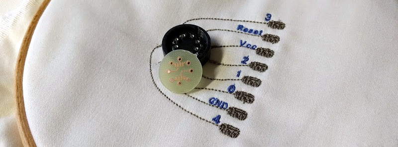
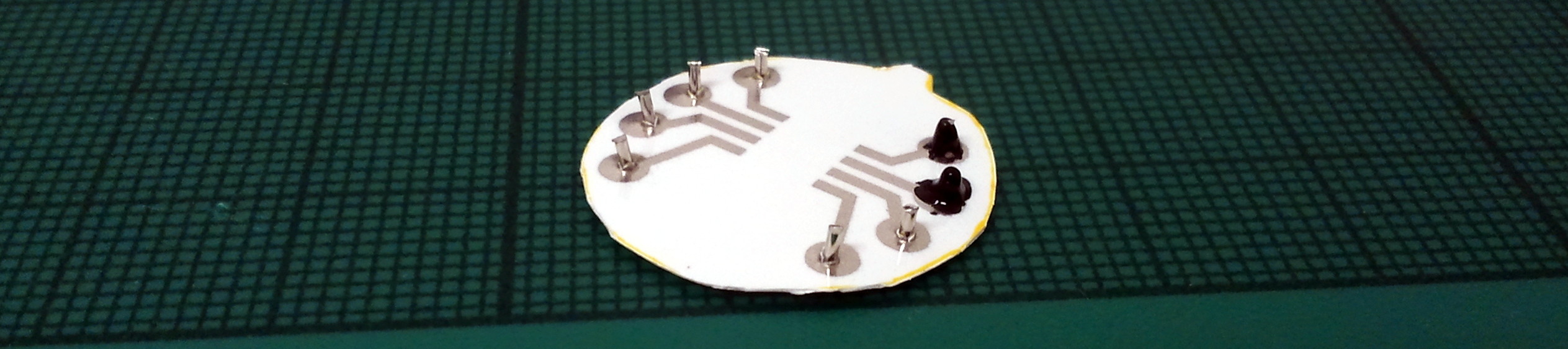
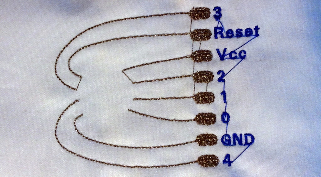
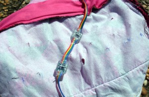
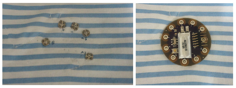
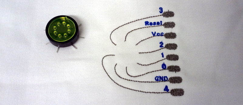
The first change made to the design was the position and size of the holes for the contacts. The first design iteration used sewing straight pins as contacts, which were handy for a very quick and dirty proof of concept, but certainly not ideal for anything more robust than that. After hunting through electronic component catalogues, I came across turned pin header sockets used for wire wrapping. The long legs of the sockets gave plenty of clearance to bend the legs out from under the button and reach the conductive thread of the embroidered circuit. The legs could then be hand-sewn with conductive thread.

The design change was to equally distribute the sockets around the PCB/button in a circle, as opposed to two arced groupings. This provided the maximum distance between the contacts and made it easier to create design files in multiple software packages for the different prototyping processes.

Print with black rubber

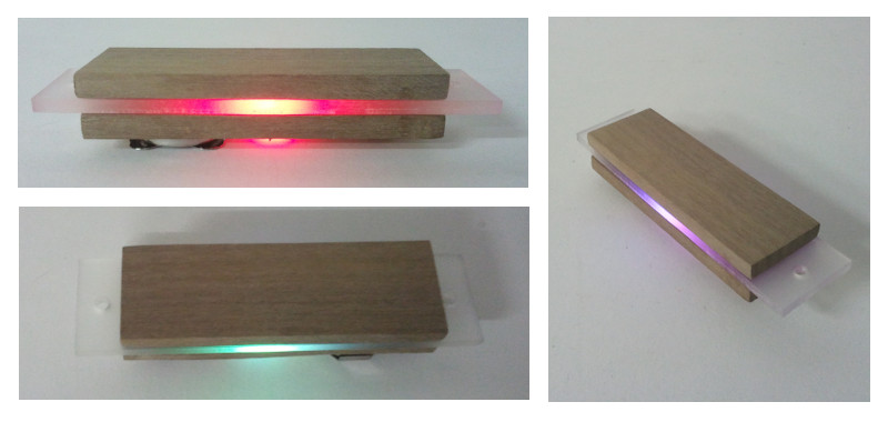
To work towards a functioning prototype, I laser cut acrylic to play the role of the PCB.

Laser cut insert

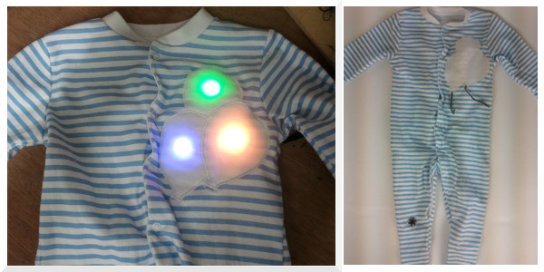
After discussing the prototype with Andrew, he pointed out that the button hole could cause too much mechanical strain on the socket legs. The stitching holding the legs in place was the only physical connections holding the button in place. To improve this, we added holes to allow the button to be stitched to the fabric directly. They were placed slightly outside the sockets so that the thread could provide a mechanical strain-relief for the socket legs.

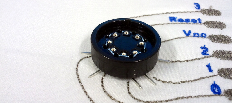
The print below uses the gloss effect in the same rubber-like plastic as the print in the photo above. The gloss effect is achieved by not surrounding the object in the support print material, but using it only where structurally necessary.

3D printed button

Milled PCB

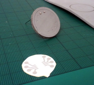
It was then time to move on to the PCB prototype. I created the design in EAGLE – with assistance from Andrew as I am far from fluent with that software tool. The PCB was then milled on the LPKF S103 PCB Mill located in the Electronics Lab at Queen Mary. Below is a PCB as it came off the milling bed on the right and after some sanding on the left.

PCBs

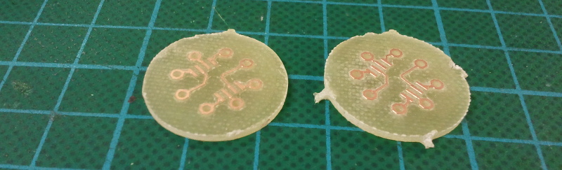
The PCB fit cleanly into the 3D printed button with all the holes lining up as they were supposed to. However, the inserting and removing the PCB and pins into the sockets highlighted a number of weaknesses in the design.

Reflections on Iteration 2

The printed material wasn’t adhered to the sockets in any way; the sockets were held in place only by the friction of the socket housing against the printed holes. The insertion and then removal of a pin into a socket caused the socket to pull away from the button.

The legs of the sockets were bent so the button could sit against the fabric, but they weren’t formed into a shape such as a loop. This meant that the force of removing a pin from the socket could cause the leg to be slid out of the stitching holding it in place.

Lastly, the 3D print material couldn’t withstand a shearing force where the rim that holds the PCB in place meets the main body of the button. The rim quickly fell apart, though anecdotally, the glossy finish seems to hold together better than the matte.

These concerns will be addressed, and hopefully improved upon, in the next and final design iteration of the project.

Button at end of iteration

Creativeworks London Project – Iteration 1

Selection of chip holders

I’ve started referring to electronics connected to soft sensors and hidden on a PCB in a pocket of a garment as the “pocket of shame”. By no mean do I mean any shame on the designers and engineers who were forced to place their circuitry in a pocket, but that it’s a shame we haven’t found a better solution. Beautiful, tactile, and flexible, textile electronic sensors can be woven, knit, or stitched into clothing, but the circuitry needed to process the data generated by those sensors or to send that data off to be processed on another device, is still often mounted on rigid PCBs.

This past October I started a short research project funded by the Creativeworks London Entrepreneur-in-Residence Scheme at the School of Electronic Engineering and Computer Science at Queen Mary University of London. I’m exploring how PCBs can be better integrated into garments with soft sensors, not by trying to transform the PCBs into something flexible, but by hiding them in the already “hard” parts of a garment – buttons.

I’m working with Andrew McPherson, a Senior Lecturer at QM, and Berit Greinke, a PhD student and lab technician in the Materials Processing Lab. We are using the rapid prototyping facilities available in the School to create buttons that are inspired by the chip holder/adapters shown in the photo above. The idea is to create a housing that can be sewn to a garment (with both conductive and non-conductive threads) that remains in place whilst the PCB it houses can be removed.

The Housing

The first design iteration has been focused on a SOIC package of an ATtiny and using the tools with the smallest barriers of use, whether cost, bureaucracy or my own skillset.

Laser cut rubber

Rubber for laser engraving

The housing has been developed using laser cut and etched rubber to make a recessed area for the PCB to sit in with 8 holes for pins to make contact with the PCB and fabric sensor.

The Circuit

The circuit was printed on paper using a Brother DCP 145C and silver nano particle ink.

I used clipped sewing straight pins as the contacts as they have broader flat heads that sat against the underside of the paper. They pierced the paper and then were electrically connected to the printed circuit with Bare Conductive Electric Paint.

The Fabric Connection

The remaining piece is the fabric circuit that the button interfaces with. With much training and assistance from Berit, I designed and embroidered a breakout circuit for the button to be sewn onto.

A Brother Pr1000e was used to embroider the circuit with Shieldex 110f 34dtex 2 ply yarn by Statex. It’s mostly done automatically, but some care needs to be taken to manually stop the machine’s thread cutter from trying to cut the conductive thread.

Here is the circuit when it comes off the machine, before trimming all the threads (which is something that can be programmed into the design for the machine to handle, but I hadn’t tackled that yet as this was my first time working with the software).

And here it is with the laser cut housing sewn in place. I used sewing straight pins to piece the rubber and then clipped the ends and formed them into loops.

Button on sewn circuit

The ATtiny was cold soldered into place on the circuit board with Bare Conductive Electric Paint and the circuit board placed in the holder.

Button on sewn circuit

A second piece of rubber served as a means to hold the circuit board in place.

Button on sewn circuit

Reflections on Iteration 1

The prototype button is able to make an electrical connection ranging from 30 to 80 Ohms of resistance from the chip leg to the sewn breakout pad. However, it is not a stable connection, but rather fragile both due to the materials and how the “sandwich” of layers meet each other.

The ability to so quickly make physical prototypes was incredibly useful, even though they are certainly not the best materials and tools to be used for the final version. Now that a general form factor has been settled on, the next iteration will utilise the 3D printer instead of laser cutting and a milled PCB instead of a printed paper circuit board.

The use of straight pins as electrical contacts were convenient as they were readily available in the lab, but won’t be used in future iterations. Another solution needs to be sourced, probably by perusing electronics components catalogues.

E-Textile Summer Camp 2015

This is a rather late report of the E-Textile Summer Camp 2015 as it ended many months ago, but it’s a post that has been on my to-do list and I didn’t want to completely abandon it.

This past July/August, around 35 experts in e-textiles/smart materials gathered at Paillard Centre d’Art Contemporain & Résidence d’Artistes in Poncé sur le Loir, France. This was the second time I attended the camp, and even though I knew largely what to expect, still came away amazed at how much I learned.

Dinner outside

Dinner outside (weather permitting, which was most of the week).

Continue reading

Barcelona Music Hack Day – Project Jane

Google announced its Project Jacquard recently. The project covers several research and development topics leading to the mass production of fabric sensors that can detect hand gestures. I think it’s a defining moment in e-textile research as it’s attracted the popular press and introduced the field of e-textiles to a consumer audience that might not have been aware of it before.

However. The announcement came via a video largely starring Ivan Poupyrev, the project’s founder. I don’t really think of project managers in Mountain View when I think about e-textiles. I think of the amazing work grown from a grassroots level that is shared with the community. Work that has historically had far more women involved than what is typically seen in tech spheres. Project Jacquard feels a little like an erasure of those contributions, so I wanted to honour them in my hack.

I decided to make a soft sensor that detects hand gestures in 24 hours at the Barcelona Music Hack Day. This is Project Jane.

Continue reading

Music Festival Bag – Midem Hack

This weekend I took part in the Midem Music Hack Day and I made this:Finished Bag

UPDATE: I won the hack! Here’s a video of my pitch presentation (starts at 9:25).

It involved flying to Cannes and enjoying this view:

View from Midem

Working on a hardware hack involving stitching was advantageous as it meant I could just sit outside and do a bit of hand sewing.

The Concept

I was inspired by the start of the music festival season in the UK and made a bag for wandering between stages. The bag is embedded with LEDs that are controlled to relay information to the wearer without needing to look at their phone.

LEDs on Bag Turned On

The bag starts with an animation to indicate it’s waiting to be connected to a Bluetooth LE device. Once a connection is made by selecting the bag from the phone’s Bluetooth device list, a general light animation starts.

The phone can send messages to the bag and instruct it to light up for particular notifications. I had it light up as all red and all green as a demo. This could be a notification that you’ve received a text message or that a show you indicated you want to attend is about to start. It alerts you to look at your phone for more information.

All the physical interactions with the bag use the tassels at the end of the drawstrings. Touch the pink tassel to the beadwork along the bottom of the to change the animation or to clear a notification and return to the animation.

Tassel

Beadwork


The blue tassel will send a message back to the phone. A potential use case would be if you ended up near a stage at a music festival and like what you heard, but didn’t know the artist, you could touch the blue tassel to the beadwork to tell a festival app on the phone to record the current GPS and time data to determine what artist in the schedule you heard. You could later refer back to that “bookmark” in the app.

The Details

I bought the bag from the Stratford Westfield from a generic mall store. It was on sale. I was looking for a patterned bag that was on trend fashion-wise and had parts that could be easily adapted into a soft-circuit interface. The woven fabric proved to be an excellent choice as it was very easy to work with.

Purchased Bag

I was lucky that the bag was constructed well and had a layer of interfacing in between the outer fabric and lining fabric. It was also complete luck that some of the beads were conductive (I hadn’t taken a multimeter with me to the store).

Bag Build

The whole thing ran on an Arduino Micro on a breadboard. It was connected to a strand of 50 WS2801 RGB LEDs and talked with a phone via the Adafruit Bluefruit nRF8001 Breakout Board. The phone ran Nordic’s demo app for working with their chips. It was a great tool. I just sent messages to the Arduino via the app’s UART interface.

Code is available on my github.


LEDS Off


School of Maaa

Still catching up on the activities of this summer. One of the closing events and highlights was spending a few days in Berlin teaching at the School of Machines, Making & Make-Believe.

I spent 3 days with around a dozen students from a variety of backgrounds. They included artists, designers and engineers. The general topic I was teaching was wearables. It was the second week of the programme and everyone had some amount of experience with Arduino.

I started my sessions with a bit of background about myself and a broad overview of the intersections of e-textiles, wearables and art. We then started with switches in the afternoon.

The big technical topic of the afternoon was the role of pull up and pull down resistors.

Continue reading

E-Textile Summer Camp 2014

Paillard

This past July I got to participate in a week-long camp that I think will remain a top highlight of 2014. I attended the E-Textile Summer Camp 2014 at the Paillard Centre d’Art Contemporain & Résidence d’Artistes. I was accepted last year, but then was gutted when my passport and visa didn’t arrive in time from the UK government to let me travel. (I didn’t know it then, but I wouldn’t receive it for another 5 months past the camp, so it wasn’t really a close call. Thanks, Theresa May.) So I was super eager to attend this year.

Continue reading

A Necklace

Necklace Exhibition

Stephanie Posavec was invited to contribute to the Futures 10 – the closing exhibition of the Wearable Futures Conference.

I was given the theme of ‘memories’. As an urban pedestrian, I often walk by memorable locations from my past, and imagine how my memories are layered upon the city over the memories of those who lived before me. I wish I could experience these memories more clearly, so I decided to create a device that would make one’s memory traces more physical and tangible. This device tags memories to a location, gathering audio and emotional data and providing a 3d-scan of the memory space. Memory maps are created over time, as personal or shared maps, and maps of past lives can be accessed by loved ones as a form a remembrance. Later, through the use of audio and haptic feedback, while walking through the city a user is able to ‘brush up’ against a 3d-texture of a memory and feel and hear important moments from their past.

Stephanie on Memories in Wearable Futures

Stephanie is an amazing visual designer and largely works with data visualisation for print, so designing an inactive wearable piece was outside her comfort zone. I think she did a great job, but she wanted some help to bring her concept off the page and make a physical prototype. We spent a day together creating the pendant for her piece.

She decided to represent the interaction through a pulsing light embedded in a necklace. She designed the light pulsing pattern and colour to show different types of memories and I got an RGB LED mocked up with an Arduino and breadboard.Prototype of Necklace

Once the colour and tempo was finalised, I programmed an ATtiny45 to do the same as the Arduino. We wanted the piece to be as small as the tech would allow, so I soldered the LED and resistors directly to the microcontroller. The pendant was constructed from two pieces of walnut wood sandwiching a piece of acrylic to diffuse the light. The circuit board was created from pieces of copper tape. The adhesive of the tape made a fairly strong contact against the wood.

Construction of Necklace

The finished pendant had a roughly 30 second cycle of 5 memories with different attributes of being personal, shared, or in remembrance.

Necklace Colours

Stephanie turned the pendant into a full necklace along with designing two boards to explain the concept. My photos and video of the exhibition aren’t great, but hopefully sufficient to get an idea of the finished piece.

It was kinda funny, and quite characteristic of those in attendance, that everyone felt very comfortable touching the pieces. The circuit on the back of the pendant was not intended for public viewing; it was supposed to hidden against the body when worn. But the necklace kept getting flipped over by curious attendees to inspect the tech.

Futures10 Necklace from Becky Stewart on Vimeo.

A Onesie

To round out 2013,  I’m going to post three projects I completed in November and December. All three were ideas that had been thought about for varying lengths of time, but were each executed in a single day. The first two, both wearable technology pieces, are more related than the third, a bingo card game.

Baby Onesie

This project was a very quick commission to provide a proof of concept for what wearable technology for children could be. It was part of an investigation for a funding bid into whether wearable tech could enhance play between parent and child.

Babyglow Onesie from Becky Stewart on Vimeo.

It was a very quick turnaround. I was approached on a Tuesday and the piece was needed the following Saturday. It was requested that the garment be a onesie or baby-grow, but that the interaction was largely up to me. The point of the piece was to demonstrate to parents in a workshop what a finished piece of wearable tech could look like as they were going to be shown other sensors and actuators outside of a finished piece.

I ordered in some kit on the Wednesday and Thursday then started and completed the piece on the Friday.

The concept was very simple: an appliqué of three balloons that appear white when the garment is not powered, light up in three different colours and then change colours when the child jumps up and down. This movement was detected by an accelerometer on the right leg.

The onesie was purchased off the high street. The appliqué was created by using several layers of white tulle as a diffuser and white cotton fabric. The tulle was an ok diffuser, certainly acceptable within the time limits and materials on hand for experimentation, but I would want to improve it if the project were to move forward. The photo looks less diffuse than it appears in person.

Appliques

The underlying electronics are three Adafruit NeoPixels controlled by a LilyPad SimpleSnap with a LilyPad Accelerometer on the leg. The NeoPixels were the breadboard-friendly version as opposed to the ones explicitly designed for soft circuits as they were the easiest to get ahold of quickly. They don’t ship with the header pins soldered on, so you can use the via holes for the header pins for sewing.

Onsie LEDs

As there were some longer runs for the circuit, I decided to try conductive ribbon for the first time. The type I chose advertised a low resistance and that it didn’t short if folded on itself. Overall, it was much better than working solely with conductive thread, but the transition from the ribbon to the components is a little awkward.

The Lilypad was attached to the lower back using snaps. The placement was in hope that it would be the most difficult place for the child to reach. It was placed low on the back so that it wouldn’t poke into them if they leaned back against something.

The SimpleSnap comes with female snaps already soldered onto the pads, which seemed convenient as I would have done that myself anyway. However, it didn’t actually come with the corresponding male snaps which was a big pain. It took a while to track down the right size snaps and now I have a handful of females snaps leftover without male pairs. However, the integrated battery is a big plus.

Back of Onesie

If I had more time, I would have created an appliqué to cover the accelerometer as well.

There is nothing particularly clever or groundbreaking in the code, but it’s up on Github.

Finished Onesie